Anodizing and Close Fits: Dimensions to Agree Before Machining
Agree finished bores, shafts, threads and masking before anodizing. Includes a clearance calculation, feature checklist and inspection questions.
Written by Jingchuan
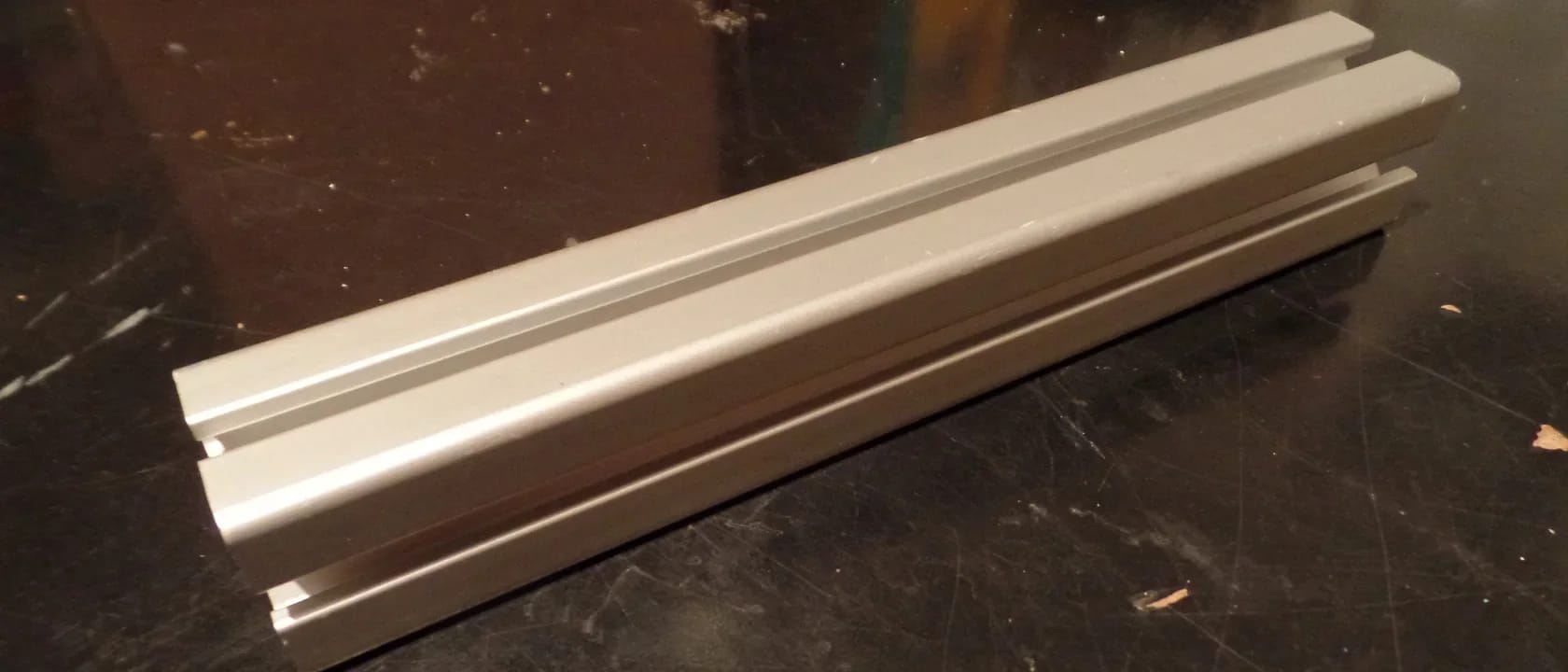
Cover: anodized aluminum profile, photographed by Dancili Fresl. Wikimedia Commons source, CC BY-SA 4.0. Cropped, resized and converted to WebP; this adaptation retains the same license. Both photographs are external examples, not Jingchuan products or verified customer projects.
Specify the finished fit before choosing an allowance
A bore can pass inspection after machining and still fail to accept its mating shaft after anodizing. The useful purchasing question is therefore: which dimensions must comply after the entire finishing sequence, and how will they be checked? Agree that answer before releasing the machining sizes.
For aluminum CNC machining, identify each critical interface on the drawing: locating bore, shaft, sliding slot, thread or datum face. State the required final size and tolerance, the condition at inspection, and whether its mating component is also coated. A generic note saying “allow for anodizing” leaves too much for the workshop and finisher to infer.
Danco Medical's hard-anodize guide distinguishes total coating thickness from outward growth. Do not treat a nominal coating thickness as the machining offset for every surface. Request an agreed allowance for the actual alloy, preparation and finishing sequence. Keep the alloy and temper fully specified.
Track both sides of a mating pair
The following is a geometric planning model, not a coating-process prediction. Let B0 be the as-machined bore diameter and S0 the as-machined shaft diameter. Let gb be the net radial movement of each bore surface toward its axis after the complete agreed finish, and gs the net radial movement of each shaft surface away from its axis. These are effective surface movements, not total oxide thicknesses. Obtain their applicable ranges from the process review; do not assume a universal thickness-to-growth ratio.
Assume round, concentric features and uniform movement on both sides. With diametral clearance C0 = B0 − S0, the finished values are:
| Quantity | Planning equation | Meaning |
|---|---|---|
| Finished bore | B1 = B0 − 2gb | Both bore walls move into the opening. |
| Finished shaft | S1 = S0 + 2gs | Both shaft surfaces move outward. |
| Finished clearance | C1 = C0 − 2gb − 2gs | Coating both parts consumes clearance from both components. |
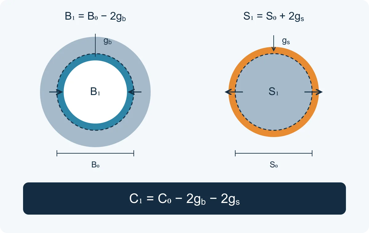
Original schematic, not to scale. Dashed circles mark the original surfaces; colored bands illustrate net surface movement, not the full oxide layer. Subscripts 0 and 1 mean before and after finishing. The parts are shown separately; their drawing sizes, geometry errors and inspection method still need review.
Illustrative numbers only: if C0 = 0.060 mm, gb = 0.008 mm and gs = 0.010 mm, then C1 = 0.024 mm. These values are invented inputs for arithmetic, not a recommended allowance or a measured process result. Counting only the bore would incorrectly predict 0.044 mm clearance.
Check the range as well as the nominal result. For assumed ranges C0 = 0.050–0.070 mm, gb = 0.006–0.010 mm and gs = 0.008–0.012 mm, the independent worst-case calculation gives C1 = 0.006–0.042 mm. This does not establish an acceptable fit. Compare the range with the design requirement and account separately for form, alignment, surface texture and measurement uncertainty. Threads require their own review; this plain-diameter model is not a thread-sizing rule.
Agree the treatment of each critical feature
Keep the design's finished requirements separate from manufacturing allowances. Have the machinist and anodizer agree the production route, then record it against the same drawing revision. The table below is an RFQ checklist, not a promise that every masking or rework option is suitable.
| Feature | Decision before machining | Evidence at acceptance |
|---|---|---|
| Locating bore or shaft | Coated, masked, or finished by an explicitly approved later operation? | Final size, applicable form requirement and inspection record. |
| Thread | Required final thread designation, coating coverage and gauge method. | Agreed thread check after the specified finishing sequence. |
| Sliding slot or mating faces | Which opposing faces change, and which datum controls the result? | Final width or spacing from the specified datum. |
| Contact or reference pad | Exact protected boundary and acceptable transition region. | Location, coverage and any specified functional check. |
| Cosmetic face | Rack-contact restrictions and the agreed appearance reference. | Inspection under the agreed viewing conditions. |
Draw the boundary when an area must stay uncoated
“Mask the hole” can be ambiguous when the adjacent face, chamfer or counterbore also matters. Mark the protected area on a drawing view and define where a transition is acceptable. Ask the finisher to confirm feasibility and how the mask will be located. If a later machining operation is proposed, get approval for the resulting exposed surface and its acceptance requirements before production.
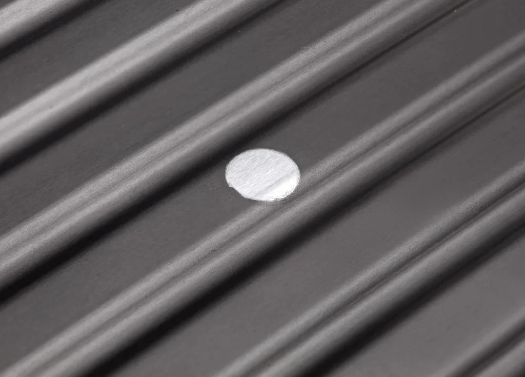
Contact-area example photographed by A Oerter. Wikimedia Commons source, CC BY-SA 4.0. Converted to WebP; this adaptation retains the same license. The photo shows a contact area, not a measured masking tolerance, a bore or an approved process for your part.
Check dimensions and coating thickness separately
Agree who measures the final dimensions, at what stage, with which method and against which acceptance limits. Also agree the coating-thickness measurement locations and records. ISO 2360:2017 covers an eddy-current thickness method applicable to many anodic oxide coatings; that is a different measurement from checking a finished bore or assembled fit.
A thickness result alone should not close a dimensional requirement. Ask whether the proposed measurement method can reach the feature and resolve the specified tolerance. Where fit is critical, define the required dimensional or functional acceptance check rather than relying on a photograph or a statement that the finish was completed.
Put the agreement into the RFQ and repeat order
Adaptable wording, not a released specification: “Dimensions identified [feature references] apply after [complete finishing sequence]. Supplier to confirm proposed allowances, coverage, masking boundaries and inspection method before machining. Alternatives or post-finish machining require written approval. Deliver the agreed final dimensional and finish records against drawing revision [revision].”
Use the CNC RFQ checklist to keep drawings and order scope consistent. Preserve the agreed route for repeat orders and flag changes in alloy, finisher or process for review. Send your drawing and critical-fit notes for a quotation, including the mating part's finish and any unresolved inspection requirements.
