Machined Electronics Enclosures: An RFQ Guide
Specify pockets, threads, connector interfaces and cosmetic faces before quoting a machined aluminum enclosure. Includes an RFQ checklist.
Written by Jingchuan
A machined electronics enclosure is an assembly interface as well as a protective shell. A quotation based only on the outside dimensions can miss the details that determine whether the board, lid and connectors fit. Before requesting a price, identify which features must stay fixed, which may change after design review, and what the finished surfaces must look like.
This guide focuses on a housing machined from solid aluminum for ordinary electronic instruments. If you want a modified extrusion, a casting or a fabricated enclosure instead, state that route explicitly. Those alternatives should not be compared as if they were the same supply scope.
1. Define the interfaces before the pocket
Send the housing and lid together with a simplified assembly model or interface drawing. Include connector manufacturer drawings when the cutout depends on a particular connector. Specify the applicable revision: a loose screenshot of a circuit board is not a controlled mounting pattern.
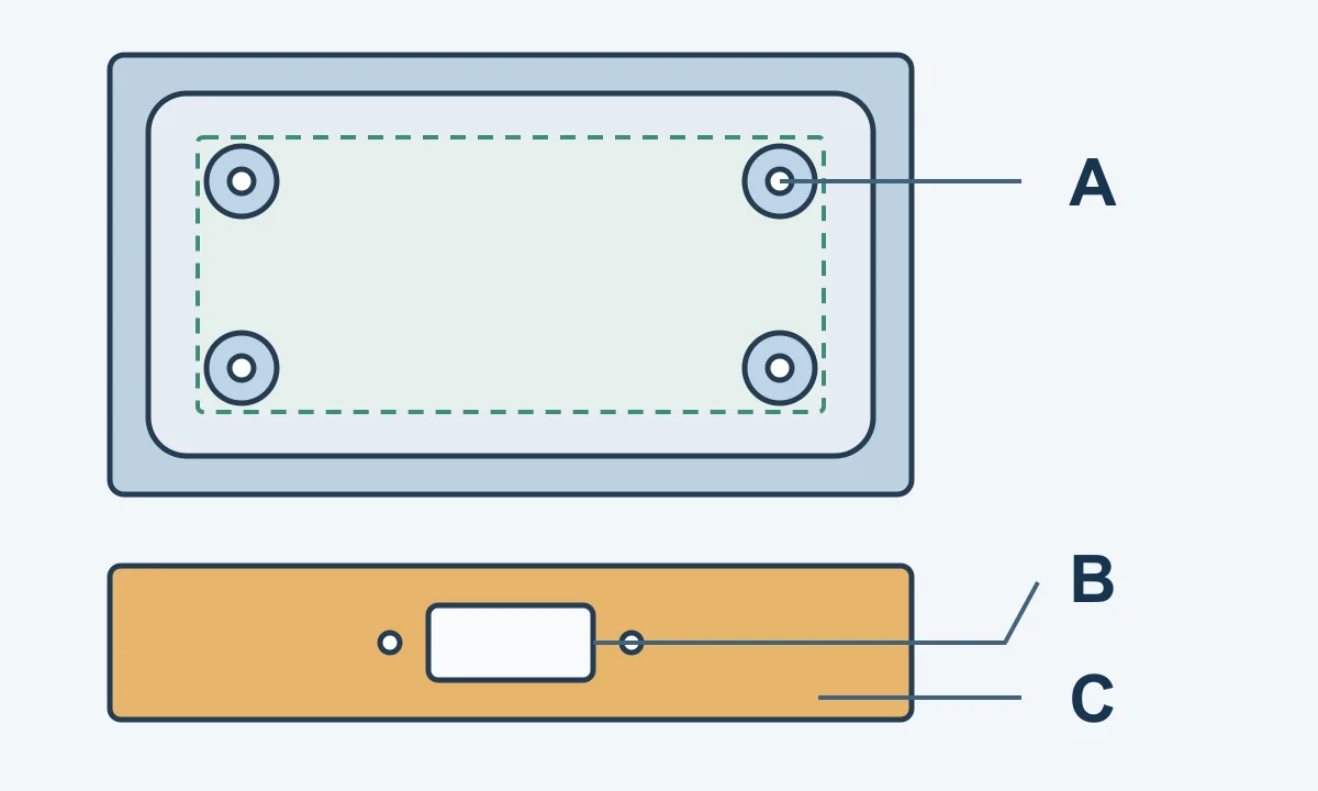
Original explanatory drawing, not a customer part or a manufacturing drawing. A: board mounting pattern. B: connector opening. C: visible exterior face. The dashed outline represents a board envelope. Geometry is illustrative; no dimensions, load capacity or sealing performance are specified.
| Interface | Information to supply | Question to settle |
|---|---|---|
| Lid and body | Mating outline, screw pattern and any seal details | Which surfaces locate the lid, and what gap is acceptable? |
| Circuit board | Mounting coordinates, board envelope and component clearances | What defines board height and orientation? |
| Connectors | Cutout geometry, fastening details and insertion clearance | Can the connector and its fasteners be installed after the board? |
| Thermal contact | Contact area, pad or spacer details and inspection requirements | Which finished surface must contact the mating component? |
Choose functional reference surfaces on the drawing so related features are measured from a consistent reference. Do not add a tight tolerance to every wall simply because one connector needs accurate positioning. Ask for any proposed datum or tolerance change to be returned for approval.
2. Separate required geometry from machining preferences
Mark the smallest acceptable internal corner radii and identify any areas where larger radii or local reliefs are allowed. Check the mating board or component against those corners; outside dimensions alone do not establish clearance.
Corner engagement affects milling stability, as explained in Sandvik Coromant’s inside-corner guidance. Ask the supplier to review deep, narrow cavities and tool access before quoting. A suggested larger radius is a design change requiring your approval, not permission to alter the supplied model.
For a thin floor or tall wall, state the functional requirement and how it will be inspected. Where relevant, distinguish free-state inspection from inspection in the assembled condition. Request alternatives as separate options, with a marked drawing showing exactly what would change. Avoid adopting a universal minimum wall thickness without reviewing the actual part.
3. Specify threads and assembly hardware explicitly
Identify thread size, pitch, tolerance class, quantity and location. For blind holes, distinguish full usable thread depth from drilled depth, and define the face from which depth is measured. The tap manufacturer’s guidance explains that a tap’s lead progressively forms the thread; tool travel is not the same as full thread length.
State whether screws, inserts, standoffs and the lid are included in the order. If an insert is required, identify its exact type and installation requirement rather than asking for an unspecified “stronger thread.” Confirm the intended screw engagement against the actual assembly stack. Thread strength and tightening torque need a design basis; they cannot be inferred from a quotation photograph.
4. Mark cosmetic faces and finish boundaries
Create a face map identifying visible exterior surfaces, hidden surfaces and functional contact areas. Agree where handling, clamping or finishing contact marks may be accepted. Record the requested finish, color reference, texture and any masking boundaries. If electrical contact is required, state the contact requirement and how it will be checked; do not leave that decision to a color note.
The Aluminum Anodizers Council identifies alloy, temper and surface condition as appearance variables. Agree a reference sample or acceptable appearance range for the actual material and process. If appearance is critical, also agree viewing conditions and the treatment of scratches, tool marks and color variation. A photograph on a screen is useful for communication but should not silently become the only acceptance standard.
State whether each critical dimension applies before or after finishing. Our guide to anodizing and close fits covers that separate dimensional question. No universal film thickness, masking tolerance or color match is assumed here.
5. Send a package that can be quoted consistently
| Package item | What to make explicit |
|---|---|
| Geometry | Housing and lid models, units, revision and assembly orientation |
| Drawing | Datums, critical dimensions, corner allowances and thread callouts |
| Material | Alloy, temper, applicable material specification and required evidence |
| Supply scope | Quantities of bodies, lids, inserts, screws and any assembly work |
| Finish | Face map, appearance reference, masked areas and final-size requirements |
| Acceptance | Inspection scope, report contents, assembly checks and protective packaging |
Request that the quotation list exclusions and unresolved assumptions. If a lid-fit or board-fit check needs a mating component, agree who supplies it, which revision it represents and whether that check is included. A fit check does not by itself establish an ingress-protection rating or electrical performance.
6. Resolve the open decisions before ordering
Use the general RFQ checklist for document control and purchasing details. For this enclosure, the useful next step is a marked drawing that closes the remaining interface, thread and appearance decisions. Keep approved alternatives with the order rather than only in an informal conversation.
For a project using aluminum CNC machining, send an enclosure inquiry with the housing and lid files, quantities and face map. List any undecided features so feasibility and supply scope can be clarified before the order is agreed.
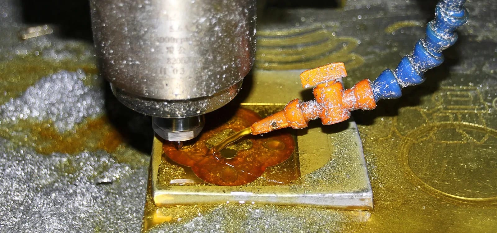
Cover photograph: Impressionmanufacturer, CNC milling machine, Wikimedia Commons, CC BY-SA 4.0. Cropped, resized and converted to WebP; the adapted photograph retains CC BY-SA 4.0. It illustrates external machining equipment, not Jingchuan equipment or an enclosure customer project. The A–C enclosure drawing is original explanatory artwork.