Threaded Stainless Parts: Drawing Details for a Clear Quote
Define stainless thread callouts, usable length, blind-hole depth, material condition and inspection before quoting. Includes two practical checklists.
Written by Jingchuan
A thread note can look complete while leaving the supplier unsure what to quote. “M6, 12 deep” may leave open the pitch, tolerance class, usable thread length and permitted drill depth. Resolve those items before comparing prices for a stainless bracket, spacer or instrument housing.
This guide is a drawing handover checklist for stainless steel CNC machining. It does not select a load-bearing joint or prescribe a cutting recipe. The designer remains responsible for the mating interface, strength and service conditions.
1. Give each thread a complete identity
Identify internal or external thread, thread family, nominal diameter, pitch or threads per inch, tolerance class, quantity and any left-hand requirement. Keep the drawing and CAD revision consistent. A cosmetic thread in CAD is useful context, but the controlled specification must settle any ambiguity.
For example, M6 × 1–6H identifies a metric internal thread with 6 mm nominal diameter, 1 mm pitch and a 6H tolerance class. It does not specify its axial length. This is an illustrative designation, not a recommended fit for every assembly. ASME B1.13M covers the metric M profile; name the applicable standard and edition on the order rather than mixing rules from different systems.
| Drawing item | Information to provide | Question it resolves |
|---|---|---|
| Thread identity | Family, diameter, pitch, class and handedness | Which mating thread and gauge are intended? |
| Number and location | Quantity, datum references and positional requirements | Which holes must align with the assembly? |
| Usable thread | Minimum full-profile length and its starting reference | How much axial thread must be available? |
| Hole envelope | Through or blind; allowed bore and drill-point depths | May the tool approach the opposite wall? |
| Entry and exit | Chamfer, counterbore and permitted runout or relief | Where may incomplete threads occur? |
| Material condition | Grade, product specification and supply condition | Which stock and process assumptions apply? |
| Final acceptance | Finished condition, checks and required records | What must the delivered part demonstrate? |
2. Separate full thread length from hole depth
Show the minimum axial length of fully formed thread independently from the total blind-hole depth. If the hole has a counterbore, identify the face from which each depth is measured. Also distinguish the cylindrical bore depth from the deepest drill-point penetration where remaining wall thickness matters.
A tap's entering chamfer has progressively developed teeth. Sandvik Coromant's tap-selection guidance distinguishes chamfer lengths by hole type. Therefore, do not equate programmed tap travel with full-profile thread length.
Ask the supplier to confirm the required clearance for its proposed tooling. Do not insert a universal “extra two pitches” allowance into every design. When the permissible hole depth is tight, resolve feasibility before releasing the drawing; changing a depth after quotation can change the proposed process.
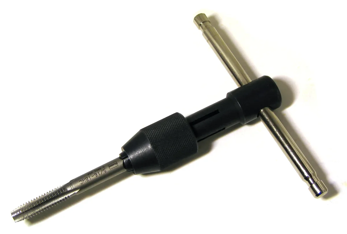
Tool illustration: a hand tap and T-wrench, not a production setup or evidence of suitability for a particular stainless grade. Photo: Omegatron / Wikimedia Commons, CC BY-SA 3.0. Resized and converted to WebP; derivative under the same license.
3. State the material and delivered condition
“Stainless” is not a sufficient material instruction. Provide the selected grade, product specification and supply condition, together with any material record requirements. Use the 304 and 316L material and inspection checklist to settle those inputs without treating a photograph or alloy nickname as proof of composition.
Separate a mandatory process from a preferred one. If tapping, thread milling or another method is contractually restricted, say so and explain the functional reason. Otherwise ask the supplier to propose a method that meets the drawing. Do not infer a manufacturing method merely from the appearance of a modelled thread.
Specify any finishing, cleaning, passivation, coating or lubrication requirements and identify the condition in which acceptance applies. If a coating is required on the thread, agree how the finished fit will be verified. Keep mating-part material and assembly restrictions in the RFQ when they affect the design; this checklist supplies no universal assembly torque or lubricant recommendation.
4. Agree inspection before the batch is made
Match the gauge to the actual thread specification. Vermont Gage's thread-gauge range distinguishes thread sizes and fit classes. A successful assembly with one shop screw is not a substitute for the agreed acceptance method.
| Acceptance item | Agreement to record | Evidence to request when needed |
|---|---|---|
| Thread size and class | Gauge system and applicable acceptance rules | Gauge identification and calibration status |
| Full thread length | Reference face and depth-check method | Recorded depth result or agreed pass/fail check |
| Position and entry | Drawing datums, location, chamfer and edge requirements | Relevant dimensional and visual checks |
| Delivered condition | Inspection stage, cleanliness and specified finish | Agreed report linked to the drawing revision and batch |
Depth needs its own clear reference. Vermont Gage's depth-measurement example shows how a counterbore can obscure a thread-gauge depth mark. Agree a readable check referenced to the specified face.
Do not copy a generic permitted number of NO-GO turns into every inspection plan. Use the selected standard's applicable rules. If a numerical measurement is required rather than a limit-gauge result, request it explicitly and agree the method and sampling. Avoid imposing an unstated 100% reporting requirement after the supplier has priced a sample inspection.
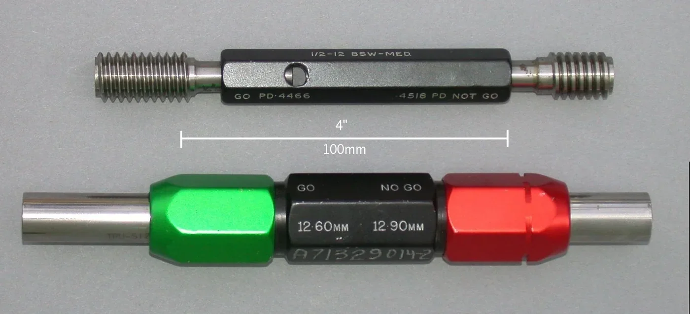
Inspection illustration: the upper tool is a BSW thread gauge; the lower one is a plain plug gauge. Neither is the M6 gauge from the example. Photo: Glenn McKechnie / Wikimedia Commons, CC BY-SA 3.0. Resized and converted to WebP; derivative under the same license.
5. Send a thread-specific RFQ handover
Consider a hypothetical instrument bracket with two blind threaded holes. The RFQ should identify both holes, the complete thread designation, their locations, minimum full thread length, depth reference, maximum permitted drilling envelope, material condition and final inspection requirements. The designer must supply the actual values; this example is a checklist structure, not a released part design or customer case.
Add the mating-interface drawing if it explains a counterbore, sealing face or restricted access. Ask the supplier to list unresolved questions and any proposed deviation separately from the quoted baseline. A change to pitch, thread class, depth or finishing must be approved and reflected in the controlled revision before manufacture.
Use the general CNC RFQ checklist for quantity, files and commercial scope. When the thread details are ready, send the drawing for a quotation, including the revision and the checks you expect at delivery.
6. Source scope and photograph credits
The linked manufacturer guidance and public standard scope support the specific points above. They do not replace the governing drawing, a purchased standard or a part-specific engineering review. No company equipment ownership, machining limit or inspection result is inferred from them.
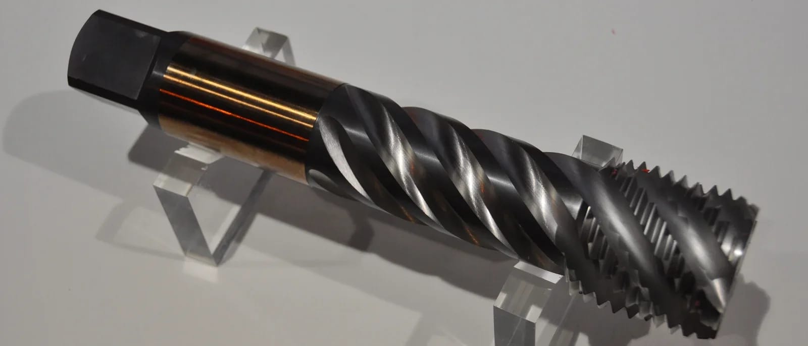
Cover: spiral-flute tap photographed by S.J. de Waard / Wikimedia Commons, CC BY 2.5. Cropped, resized and converted to WebP. All three photographs are external illustrations, not Jingchuan equipment, products or customer projects; they do not identify the workpiece alloy.